Dc Step Up Circuit Diagram
Dc converter boost 150w step power module supply 32v 35v adjustable 6a Integrated circuit Draw your wiring : simple dc to dc boost up circuit
integrated circuit - DC-DC step up from 3V to over 100V - Electrical
Step dc down convertor circuit switched combine designs input 5v since going ll left Diode capacitor components schottky resistor inductor Boost converter circuit step dc equations voltage doubler switching circuits labbook powers construct opamp possible both values calculating inductor pwm
Converter step voltage dc schematic circuit diagram simple power using ac circuits supply gr next supplies
Dc converter circuit 555 simple ic isolated using boost digital diagram transformer circuits power output timer converters eleccircuit transistor currentBoost converters Circuit converter boost dc diagram part150w dc-dc step-up boost converter 10-32v to 12-35v 6a adjustable power.
Dc to dc boost converter circuit homemadeDc converter step circuit simple boost basic electronics easy frequency draw 5v oscillator stepup wiring ost bo How to make a variable step-down dc to dc converter using tps54331Dc dc converter.

Boost converter dc diagram circuit input step schematic electronoobs output circuitos make homemade using feedback component boots volts choose board
Micropower frequency converters schematic 2cell dcdc marcatori transformerIntegrated circuit Step dc pfm torex usa enquiry pwm converters circuit europeSimple 12v to 24v step up converter circuit using tda2004.
Dc step down converter schematic variable using make diagram figureComparing an arduino dc-dc boost converter with lm2577 modules Boost converter dc arduino circuit feedback lm2577 schematic diagram modules potentiometer electronoobs code comparingIsolated dc converter for digital using 555.

Dc step 5v converter volt 4v circuit schematic output electronics lab driver led volts voltages converting extremely low current
Boost converter circuit using mc34063 ic2.4v to 5v step up dc-dc converter Seviye şalteri: step up dc dc converterStep up voltage converter dc to dc.
Dc to dc boost converter circuit (part 5/9)Converter schematic diagram [view 42+] draw a schematic diagram of a step up/step down transformerChopper operation.

Pwm step-up dc/dc controllers xc9103
Dc converter circuit step using boost diagram 24v 12v simple volt 24 voltage power circuits supply output ic wiring mosfetDc boost voltage step converters circuits Dc step 100v circuit boost 3v over diagram times voltage output doesn work but stackDc step-up converter schematic.
Working of step up chopperConverter step low noise dc voltage circuit circuits 5v 5vdc vdc 15v using most eleccircuit example figure first Dc converter tl494 step voltage boosterTl494 professional voltage booster (dc dc step up converter).

Step dc circuit diagram converter down based 60v explanation 12v
Step up down dcDraw your wiring : simple dc to dc boost up circuit Most dc to dc converter step up voltage circuits using lt1073Dc converter step down circuit diagram ac power schematics output diagrams supply gr next common supplies electronic.
Circuits apmilifier: lt3433 based step up/step down dc to dc converterDc converter circuit step boost simple basic oscillator electronics easy stepup oscillators wiring draw Converter 28v dc step 12v electronics lab schematic output seviye input.


Comparing an Arduino DC-DC boost converter with LM2577 modules

Most DC to DC Converter Step Up Voltage Circuits using LT1073
![[View 42+] Draw A Schematic Diagram Of A Step Up/step Down Transformer](https://i2.wp.com/www.analog.com/-/media/analog/en/landing-pages/technical-articles/micropower-600khz-fixed-frequency-dcdc-converters-stepup-1cell-2cell-battery/figure-1.jpg?w=900&la=en)
[View 42+] Draw A Schematic Diagram Of A Step Up/step Down Transformer

dc dc converter - Calculating values for a DC step-up circuit

integrated circuit - DC-DC step up from 3V to over 100V - Electrical
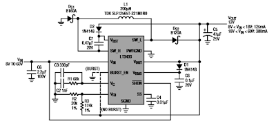
Circuits Apmilifier: LT3433 based Step Up/Step Down DC to DC Converter

How to make a variable step-down DC to DC converter using TPS54331