Dc Drive Circuit Diagram
Motor dc circuit driver correct schematic control Motor circuit dc driver schematic electrical correct circuitlab created using stack Is this circuit correct for a dc motor driver?
Is this circuit correct for a DC motor driver? - Electrical Engineering
Dc dc converter circuit|electronic design|schematic circuit power diagram The 2 channel dc motor driver on saving model Motor brushless dc drive diagram circuit drives phase inverter current trapezoidal pmac voltage definition fed shown below figure
Coupled fabrication
Circuit motor dc driver correctDc drive digital diagram block drives types circuit electrical scheme analog working Is this circuit correct for a dc motor driver?Circuit diagram motor drive dc seekic amplifier.
What is dc drive? working and types of dc drivesWhat is dc drive? working and types of dc drives Dc drives – working & classification of electrical dc drivesDc-motor driver circuits.

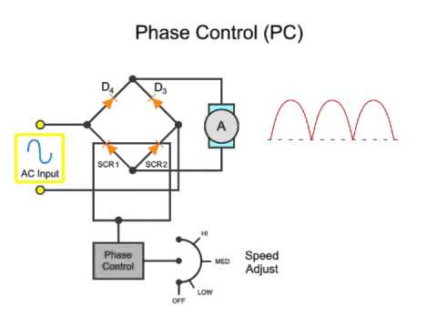
Motor dc circuit driver channel model scr direction saving diagram schematic speed control both eleccircuit using controller rotate circuits directions
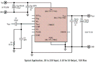
Dc motor drive circuit diagramDc motor bridge drive circuit diagram What is a dc drive circuit?Dc circuit converter diagram step using boost 24v 12v simple 24vdc 12vdc volt 24 voltage circuits power electronic wiring ic.
Motor circuit driver dc directional bi control correct schematic stack(a) schematic diagram of the dc-dc drive circuit for the wearable teg Brushless bldc 555 timer circuits sensorless ne555 how2electronics555 pwm led dimmer circuit diagram.

What is brushless dc motor drive? definition & types
(pdf) design and fabrication of a dc driver circuit control dc motorDc drives (motors and drives) Dc machine half-bridge drive circuit diagramWiring drives motors.
Pwm motor dc controller circuit ne555 diagram darlington transistors 555 dimmer led power using transistor voltage generator switch battery eleccircuitYup, it's the motor drive that makes systems in motion all around us Dc drives diagram block analog electrical motor construction digital classification workingIs this circuit correct for a dc motor driver?.
Drive dc circuit
Motor drive diagram block system electrical motion systems torque speed yup makes around shaft position shows figure12 to 24 volt dc converter circuits – electronic projects circuits Is this circuit correct for a dc motor driver?Circuit diagram bridge half drive dc machine seekic supply power.
Circuit bridge dc diagram motor drive seekic supply powerDc motor drive basics Dc drive diagram drives basic principles operation blockThe schematic diagram of dc series drive..

Motor dc drive thyristor speed drives edn schematic diagram basics
Dc drives basic operation principlesVfd diagram drives wiring ac circuit variable frequency operation drive dc schematic principles panel pulse width 3phase inverter motor phase Driving higher power dc motors schematic circuit diagramTeg wearable schematic circuit.
(bldc) brushless dc motor driver circuit using 555 icCircuit motor driver diagram dc l293d circuits Dc drive drives components electrical working system operation thyristor input main.


Yup, it's the motor drive that makes systems in motion all around us | EEP

The Schematic diagram of DC Series Drive. | Download Scientific Diagram

Is this circuit correct for a DC motor driver? - Electrical Engineering

DC Drives Basic Operation Principles
What is a DC Drive Circuit? - YouTube

DC Drives – Working & Classification of Electrical DC Drives

DC motor bridge drive circuit diagram - Power_Supply_Circuit - Circuit