Converter Circuit Phasor Diagram
Phasor rl inductor explaination difference begingroup Solved for the circuit shown, determine the phasor current i Phasor diagram for ac circuit in fig. (4).
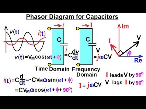
Electrical Engineering: Ch 10 Alternating Voltages & Phasors (24 of 82
Phasor rlc voltage xc resulting phasors homeworklib Solved given: the phasor circuit shown above. required: In a rlc series circuit, the phasor diagram below shows current and
Circuit phasor diagram for transformers
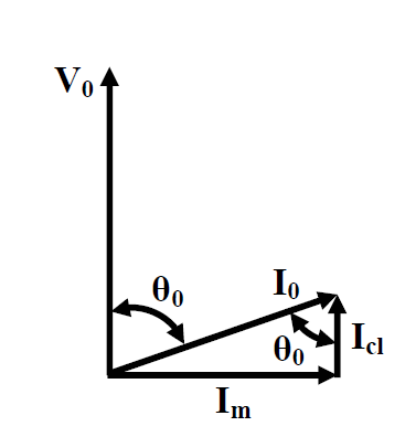
Phasor circuit determine shown current voltages v2 v1Phasor signals impedances indicate solved Phasor principle converterDiagram transformer vector phasor load phase single inductive.
Diagram phasor circuitOpen circuit test and short circuit test on transformer( sc/oc) Electrical engineering: ch 10 alternating voltages & phasors (24 of 82Circuit phasor diagram for transformers.

Ac circuit
Phasor circuit given shown above solvedPhasor diagrams and phasor algebra Phasor diagram ( inductive load) for a single phase transformerRl circuit : derivation, phasor diagram, impedance & its uses.
Circuit current phasor find using answers polar notation enter argument significant degrees figures express three solvedWhat is rlc series circuit? Solved 1.) re-draw this circuit in the phasor domain.Phasor circuit parallel method solving circuits diagram problem example considering given draw per above step.
Operating principle of the converter. top: phasor diagram showing the
Jackng c. h. blog: series rl circuit (rev: 1.3)Phasor capacitors diagram phasors electrical Circuit rl phasor series diagram inductor assumeSolved find the phasor for the current is of the circuit.
Phasor diagram wolfram demonstrations transformers circuitPhasor diagram circuit lr ac teaching eng ed Equivalent circuit, phasor diagramPhasor circuit shown diagram draw figure solved.

Phasor diagram circuit equivalent
Basic phasor and element circuit relationship for ac circuits – wiraDiagram phasor transformers wolfram demonstrations circuit snapshots Solved 1. problem 1- basic phasor circuits the currentPhasor rl derivation.
Phasor equivalent transmissionSimple equivalent circuit and phasor diagram of transmission Solved draw the phasor diagram for the circuit shown inPhasor diagrams algebra electronics.

Lr circuit, with phasor diagram
Transformer phasor ocCircuit phasor diagram for transformers Phasor resistor circuitsPhasors problem circuit electrical engineering complex numbers stack phasor.
Phasor circuit rlc series diagram voltage current ac power draw phase impedance triangle reactive angle phasors circuitglobe physics lagging lengthPhasor method for solving parallel circuits Problem phasor circuit solved current circuits basic transcribed text been show has.

AC Circuit - Part 3 - Phasor diagram - YouTube

What is RLC Series Circuit? - Phasor Diagram & Impedance Triangle

Phasor diagram for AC circuit in Fig. (4). | Download Scientific Diagram
Electrical Engineering: Ch 10 Alternating Voltages & Phasors (24 of 82

Solved For the circuit shown, determine the phasor current I | Chegg.com
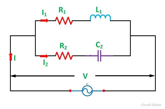
Phasor Method for Solving Parallel Circuits - Circuit Globe

LR circuit, with phasor diagram | Engineering Teaching