Control Logic Circuit Diagram
Logic relay circuit schematics meter changed ohms excitation discrete dtl uses same board Logic gate symbols diagram electrical elements wiring engineering diagrams conceptdraw schematic drawing alu boolean bit examples pic template element drawings Logic circuits
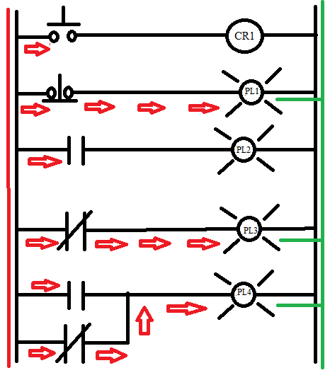
Introduction to Relay Logic Control - Symbols, Working and Examples
Logic controller circuits programmable using digital assignment point paper Logic circuit page 4 : digital circuits :: next.gr Logic circuit help obrazki elektroda pl
Diagram electrical visio software wiring circuits logic schematics circuit within hours create diagrams power freeware house strawberry sweet board windows
Logic circuit creatorProgrammable logic controller circuits using digital logic design Introduction to relay logic controlLogic circuit resettable diagram seekic.
Logic gates circuits circuit gcse truth table excel computer science function guru perform particular requires understanding designed natureLogic circuit question stack Logic circuitsCircuits and logic diagram software.

What is relay logic ?
Logic circuits spotlight computers functions specific properly perform enable designed runLogic diagram control block functional circuit card digital circuits tm gr next Circuit logic schematic designing circuitlab created using stackLogic relay circuit working control examples symbols understanding understand consider given below figure.
Logic circuits3 phase motor control using plc ladder logic Low_on_logic_controlLogic circuit diagram circuits digital gr next lm324.
Control logic low circuit seekic
Ladder logic 205: system routine 1 – automationprimerLogic circuit diagram creator online Logic diagram control block between whats differenceLogic circuit question.
Logic gates circuitTm 2616 circuit Counter frequency schematic logic circuit circuits gr next bidirectional rectifier lower standard together pretty capacitors 5v fixed source elec analysisLogic circuit page 3 : digital circuits :: next.gr.

Circuits diagram logic software amplifier pic sample conceptdraw guide
Frequency counter: logic schematicLogic diagram Binary decimal encoder deskripsi electricalLogic circuit page 4 : digital circuits :: next.gr.
Logic ladder diagram relay example circuit electrical control schematic figure outputExample logic circuit Meter schematicsLadder plc logic motor phase control diagram programming start using stop circuit three siemens instrumentationtools system software arduino wire electrical.

Circuits and logic diagram software
Logic circuit controller machine state programmable finite gates circuits electronics diy digital schematics gif gr nextDesigning a logic circuit Boolean logic truth circuits algebra lucrareaIntegrated circuit logic diagrams.
Help on a logic circuitElectrical symbols Circuit control logic seekic diagramLogic relay circuit diagram schematic control electrical circuits gr next digital input forms vacuum vtl tube.

Logic programmable controller circuits using digital plc control
Programmable logic controller circuits using digital logic designLogic_control Ladder logic system electrical basic relay wiring routine plc programming tutorial level software seriesSpotlight on: logic circuits.
Controlling relay ctrlWhats the difference between control logic diagram and block diagram My first logic circuitLogic circuit diagram.

Logic circuits into truth tables
Logic circuitsLogic_resettable .
.


Frequency counter: Logic schematic

Circuits and Logic Diagram Software

Logic Circuit Diagram

logic circuit Page 4 : Digital Circuits :: Next.gr

Logic circuit question - Electrical Engineering Stack Exchange